Monday 30 November 2020

Polar Mesospheric Winter Echoes reappear.

High above 69 degrees North, PMWE, the winter apparitions of PMSE, have appeared very strongly again.

Anyone interested in high latitude-crossing DX paths on higher HF and lower VHF may see some interesting results, although the ability of PMSE/PMWE to sustain propagation is not proven.  

With that caveat in place, it is nevertheless interesting to note extremely good propagation at 12m over the past couple of days, extending, according to time of day, to coverage of most parts of the globe.  

About 40 minutes before sunrise here today, two-way 24MHz FT8 signals from as far as India were at good levels, with the first signals already present at about 07:15UT.


My received signal reports at 08:05UT


Saturday 28 November 2020

24MHz today.

Believe it or not, the screenshot below is not of 14MHz activity this morning, but 24MHz. 

And my coverage so far today, before lunchtime:

Yesterday was also good, with solid SSB QSOs into the US, one station using a simple vertical.

Roll on, Cycle 25!


Friday 27 November 2020

Careful how you test antennas!

I was out well before sunrise at the east-facing beach this morning, during a flat-calm, clearing sky.

This mission was to test out a single turn magnetic loop of 10mm microbore copper, which was recycled from a successful 'figure-of-eight' project a couple of years ago.

The loop is only 2.5m in circumference, or a little under 800mm in diameter.  It's fed with a 'pseudo gamma match', via a 4:1 balun.

Mounting things securely in the field is one of the biggest headaches with this antenna type.  I found a timber stand blew down without guy ropes.  Ropes are not ideal in the field, as they take time, space and represent a trip hazard for other beach-goers.

So, last night, I drilled two holes in the L-section steel I have, which was made initially for a 10m fishing pole.  With bolts and a couple of wing nuts, the permanently-fixed loop, capacitor and balun just slip onto the steel really quickly.  Tuning with my homebrew remote system proved very quick, stable and gave a perfect match for 14MHz:

L-section steel driven into the ground makes a sturdy support.

Now, when it comes to analysing the 14MHz WSPR results, this antenna is tough going!  Why?  Because it is both directional and has a relatively narrow beam, notably with vertical radiation (i.e. to the left and right of the loop above).  So simply looking up every station isn't going to work - especially when, as in late November, the path from places like VK and ZL is variably long and/or short path, which serves to complexify things a lot!

Here's a pretty rubbish video I made with the current meter showing how the radiation changes quite quickly with position.  Note also that, perhaps surprisingly at the beach, that the near-field radiation pattern is not especially low.  Singal is peak when the needle is at the bottom of the meter in this video:


And for completeness, here's the radiation perpendicular to the plane of the loop, which is purely horizontally polarised:

Overall, I wasn't able to find non-long path DX stations that were within the reasonable line of fire of the vertical beam.  That said, I did find that this tiny HF antenna at the beach reached ZL1ROT at -22dB, exactly matching the signal achieved by my vertical delta loop back home (which has a much better aspect to the antipodean point, mid-Atlantic, which is not a favoured direction for today's beach location).

RZ3DVP was reasonably close to the peak beam in the vertical plane.  The magloop was 3.5dB weaker than the vertical delta loop at home, despite having the sea to help it.  The exact-same difference was seen with OH3FR, and pretty much the same (-4dB) for RX-only JMBNSWED in Sweden.

I'm now starting to wonder whether the loop might actually work better if it is closer to the ground, than about 1.5m above it?

In fact, my inveterate antipodean eccentric counterpart, VK3YE, got to this question a long time ago, and seems to answer it quite conclusively, albeit by moving the damned loop far too quickly for us to get a good grip on what's happening.  In his video, it seems the received signal is better at around waist height than over his head or much closer to the ground, although it's a question as to whether he is receiving with vertical or horizontal radiation when he holds the loop vertically - both radiation types are in effect in that orientation.

Inevitably, I will have to test this out again, perhaps from my west-facing coast, where the long path is clear and assisted by the sea.

Tuesday 24 November 2020

Monster sunspot

Not much time between the appearance of new sunspots all of a sudden.  A huge spot, showing a marked Wilson effect, has just come into view in the past day or so.

Interesting radio times may be ahead!


Monday 23 November 2020

G3 Conditions brings WSPR alive

Very disturbed geomagnetic conditions overnight.  This brought beautiful enhancements on 14MHz WSPR.


TF4X,inside the auroral oval, received my 1W with a big spike at around 01:30UT, as a field disturbance pulse got underway. As that pulse died, another began about an hour later, bringing another pre-dawn peak:

TF4X reception of MW1CFN 1W WSPR 22-23/11/2020

The 01:30UT peak was also clearly seen in OE9GHV's reception of my signal (note different time scale to previous plot), but not the later disturbance:


Sunday 22 November 2020

Big Winter Mesospheric Echoes break out

Very strong high latitude polar mesospheric winter echoes have broken out in the past 24 hours.  I wasn't active on the bands today, so I wonder if there was any 6m or higher HF enhancement?

The second plot shows the situation 24 hours later, with an intensification in echoes.

PMWE echoes at 53.5MHz/  MAARSY/IAP Leinbiz Institute for Atmospheric Research.


Friday 20 November 2020

E-bay find of the month

I'm delighted that there's been a fair bit of interest in the cheap loop idea.

Perhaps the only real problem with loops is their extreme sensitivity to tuning - which of course is why they are also good for receiving, as they reject pretty much everything outside an incredibly narrow 'window', such as that depicted below:


Whilst a motorised tuning system is pretty easy to construct from cheap components, a manual system is more useful in the field, as there is no need for batteries.

But it can be tricky to hit the 'sweet spot' reliably, especially near the self-resonance point of a loop.  A drive reduction system is desirable, if not essential.

So, I was happy to find this pretty vintage 10:1 reducer last week for about £14, not much more than the new, but far more basic and coarser 6:1 units you can find also on E-bay.


If you are going to get a reducer, keep in mind that the body of the drive has to be secured somehow, otherwise it has nothing to turn against.  This is sometimes not so easy to arrange.  This unit has holes through which it can easily be secured to a panel or frame if needed, but I found that, with the help of a single turn of self-amalgamating tape, it would fit neatly into a 22mm PVC pipe clip.  Very simple, for once!


14 Hour reception of long path VK3QN

Latest 14MHz reception of VK3QN (long path-directed), showing a ~14 hour period now, with the strongest peak an hour or so before local solar noon, and a collapse commencing immediately after local solar noon (12:02UT on 19/11/2020), showing that the long and short path contribute to this near-noontime peak:

VK3QN 14MHz WSPR reception at MW1CFN, 19-20/11/2020.

UPDATE: Another long period of reception followed on 24-25/11/2020, with a much broader period of peak signal, which was 3dB stronger than the preceding example.  Also a recovery after solar noon for a short period, before crashing into the noise:


Wednesday 18 November 2020

What the hell?

I managed to get some time to read more of this month's Practical Wireless during the past evening.  

On the cover is a picture of something that looks like the tail of a kite.  It's actually an antenna wire sewn into some plastic fabric that slides over a telescopic fishing pole, making a multiband end-fed.

They call it...the Bantenna.   Oooohh!

The review, which somehow manages to stretch to two pages, says that the sleeve design might help to make onlookers less suspicious of your radio activities. 

Well, if putting up a 7m fishing pole isn't suspicious enough for the suspiciously-minded, then sticking a bright red sleeve over it (black also available(!)) is hardly going to make them turn away and go 'oh, it's just harmless radio, pour the wine, Donald'.

Of course, it gets worse.

Asking price for a (probably) 9:1 unun with a bit of wire and some material over it?  

£125 if you want a pole with it. £95 if you don't.

Arrrrrrgghhhh!!!  

A toroid for a 9:1 costs roughly £7 for a decent one.  Maybe a couple of metres of enamelled wire for the windings, add another £3, maximum.  Connectors?  Well, those can be just auto spade types, costing almost nothing, and that we all have anyway.  You don't need a plastic box over the unun, but it might set you back all of £3 if you really had to get one.

7m of wire: roughly £7, if you bought some decent kevlar-cored stuff that doesn't tangle.  Most of us already have junk wire.  Bantenna Man calls this 'feed wire', when it's actually the radiator.  It's also the first time I've seen a radiator wire connector on the same side of the unun box as the coax connector - not such a good idea when the current maximum is as close as you could make it to the coax input.

Also note the use of a forked spade connector for the radiator.  Anyone who has worked radio in the field will know these are generally a bad idea, because they easily work themselves loose when there is any mechanical movement going on (such as a wildly flapping fishing pole!)  Don't copy this man: use ring connectors that can't pull themselves out.

Now the big cost: the telescopic pole, which have gone up substantially in price: now about £20.

Let's add all that up, and we get: £37.  You can just tape, hang, or cable tie the wire to the pole.  The sleeve idea seems to me, from the monumentally crap video (below), to be more of a headache than if it were not there.

You can in fact buy (if you want to buy anything) the same type of end-fed antenna from the Hawaii Emergency Radio Club for only a bit more - $56 - and, I can testify, is well worth considering for a basic, portable multiband solution, even if it's not the best antenna in the world.

What a total joke!  £125 for a simple end-fed antenna.  The only thing that Bantenna's owner should put a sleeve over is his microphone, because in his advertising video online, you hear more of the wind than his hot air about the antenna.  The man also can't spell: "Imagine an antenna that hides in plain site [sic]".  

Unsurprisingly, the owner tells us on his site: "We are not VAT registered, we don't have to be".  That's because he doesn't (and probably never will) make enough money from his wire-in-a-sleeve to require VAT registration (currently £70,000 per annum). 


Cheap loop

OK.  First the last few words about the 'John Loop', my poor man's homebrew of the £300 'Alex Loop' magnetic loop (coax cable) antenna.

With the loop still propped up against a chair in the kitchen, I sent 1W WSPR at 14MHz for a few hours.  Whilst it was still just about working, I applied the tools of DXplorer to the results.  They're pretty good.

Both these comparisons are with the stations who were reporting the largest number of spots from the UK, but both were using 5W, or 7dB more power than I was.  All reports are for DX distances, in this case, beyond 4000km:

Here, I am 6.3dB worse than G4UGD, but he is using 7dB more power, hence I am ~1dB better at DX distances.

 
Against G0IDE, I am 3.6dB stronger at DX distances, despite using 7dB lower power.  Hence, I am actually over 10dB stronger on a Watts-adjusted basis.


And good also against G8YPE, where the Watt-for-Watt comparison is ~3dB stronger at DX distances for my loop.


For those of you of a more gun-toting, Trump voting persuasion, remember that none of these results rely on any human involvement.  I just built a coax loop, sat it in the kitchen, and let it do its thing, automatically.  

And once we're finished?  Just roll it up and stick it in a bag.  The only thing to perfect is the support for field use.  I'm thinking pipe clips of some sort to attach the capacitor to PVC tube, and maybe a ground spike.  A tripod, the common solution, isn't really stable enough for windy places with such a top-heavy load.

It all rolls up into this small package.  Ruler is 15cm.  The capacitor has changed again, mostly because the vane contacts were easier to clean and maintain.

And for a floor-mounted, tidy version, have a look at this fine construction:


DXplorer for WSPRlite Users.

Thanks to the SOTABEAMS' WSPRlite 'matchbox' transmitters, WSPR use has grown a lot in recent years.  

A useful feature of the WSPRlites is that, as a buyer of the units, you get to use 'premium' features of the software, DXplorer, which produces plots and comparisons of your data with others'.

Some months ago, I was told by the then managing Director of SOTABEAMS, Richard Newstead, that the company was no longer maintaining the DXplorer site.

DXplorer is useful for quick comparisons with others, although I was always a critic of the use of arithmetic mean for these particular calculations, something which SOTABEAMS refused to accept.

This week, with DXplorer taking a very long time to produce any output, and often simply returning a 'timeout' error with no output, I contacted SOTABEAMS to advise them of the problem, hoping that they might at least want to get the site back up and running properly, even if they no longer actively maintained it.

This time, under a new Managing Director, I was told that the company is in fact still maintaining the site, just "not as a high priority at the moment."  

OK, these problems do occur, not least when they rely on the WSPRnet database, which itself can often hang up badly or completely - although that hasn't been the case for front-end users this week.  And SOTABEAMS do seem to be willing to address the problem.

But I am a little uncomfortable with so many WSPRlites having been sold to the world, only for the seller to then see support for all the users of those products to be sent down the priority list, such that the site doesn't work, and needs us to prompt them to do something about it.

There is also a question as to what extent the advertising of WSPRlite units on the SOTABEAMS website might be said to be in breach of UK advertising rules.  There is the clear association of the WSPRlites with 'premium' access to DXplorer, effectively meaning that buying a WSPRlite is also buying that access to the software.  Put another way, if you don't buy a WSPRlite, you do not get that 'premium' access.  

SOTABEAMS' website (accessed 08UT, 18/11/20) clearly shows it is marketing WSPRlites partly on the basis of full access to DXplorer - which it now says is a site of reduced maintenance priority.
 

If the software doesn't actually work, or is allowed to deteriorate without any attention being paid to it in reasonable time, then is that a breach of advertising rules?  Only the Advertising Standards Authority are authorised to judge.  

Certainly, it leaves a bit of a bitter taste in the mouth.  Whilst we can do our own manual analyses of data, DXplorer certainly does - or did - make a huge improvment in the efficiency of those analyses.  So its present moribund state is a cause of considerable disappointment, especially when SOTABEAMS has a good reputation of trust - on which I hope the new MD understands he really does depend.

The obvious solution to these kinds of problems, though less welcome, is to ask for a modest annual subscription for software use.  This is something I've also argued should apply to WSPRnet, which has plenty of its own problems from time to time.  

The other solution, which also gets around the problem of the ham community being dependent on proprietary software that might later be abandoned, is to make DXplorer and its ilk open source.  


Sunday 15 November 2020

The day I rediscovered radio.

Well, it's been a true 'junk box' end to the week, when the increasingly rare leftovers from other projects have been recycled into an analogue of the 'Alex Loop' (£300) magnetic loop antenna.

The RG213 'junkbox' loop, proving definitively that solder and food do mix!  Note the 'sausage' shaped primary loop, which also extends a bit outside the main loop.  This gives the best coupling to the secondary loop, and is a form recommended by many experienced loop users over the years.
 

For the most part, this is an exercise again to show newcomers that magloops can be made very cheaply, are not as mysterious and impossible to build as some make out, and are effective solutions to multiband operation, needing hardly any physical space.

The leaning tower of Pisa is about 60m tall.  A loop just 1m in diameter sends out waves that long!
 

Well, to test things out to the extreme, I located my magloop, made of RG213 cable, in the kitchen, and went 5W /QRP for real FT8 QSOs - on 60m!

As predicted, I did have to change the capacitor for a wider-space version (a Jackson Brothers 15-500pF unit).  Tuning by hand at 60m is fairly easy and reliable, but gets progressively 'twitchier' as we go up the bands, and becomes impossible by 20m.  This can be rectified with a simple PWM motor, or a different capacitor range. 

New, wider-spaced capacitor.  If you build a loop, don't space the SO239's as closely as I have here (I was in a rush to test the cap), because they affect system capacitance too much.  Space them 10-15cm apart, and tuning will be a bit less 'twitchy'.

The first thing to note is that a magloop calculator, such as this one from 66 Pacific, will throw out an efficiency for this particular loop of about 3%.  With 5W going in, this should mean my real output signal is a mere 150mW.  

Is this calculation correct?

Almost certainly not.  The reasons why are eloquently set out by Professor Mike Underhill, G3LHZ, in a chapter entitled The Truth About Loops in the International Antenna Collection book by the ARRL and RSGB.  It is well worth a careful read, notably the parts about the persistent misinterpretation of the Chu-Wheeler criterion.  Prof. Underhill concludes that, at lower frequencies, the conventionally-computed efficiencies (lower, very faint curve in plot, below) for magnetic loops are up to 30dB in error - something he terms "a scandal".  A loop-related paper by Underhill can be found at Scribd.

Returning to my tests, I wouldn't say that QSOs are impossible at 60m with 150mW.  But they might be very few, and weak.  

This was most certainly not my experience this weekend!

For example, I was very happy to make a good QSO with my friend PE4BAS, who kindly then sent me a screengrab of the current reports:

For sure, I was very happy to see these kinds of reports from several locations across Europe, and I was effectively working a slow pileup on 60m for a long time on Saturday afternoon.  The use of QRP power certainly seems to bring out the best in the radio community, with people making a genuine effort to support a low-power operation.

In the morning, I received a -15dB report from K1HTV, though he seemed to be only receiving at the time.  I was also especially happy to make a QSO with TF3DT.

60m FT8 activity with my 5W and loop, past 24 hours.

There aren't so many international WSPRers on 60m, but the pattern (using 1W) reflects the FT8 activity:


I havent' enjoyed radio this much for a while.  Operating on 60m ordinarily would need a dipole of 30m length, or a vertical of 15m.  Those are not possible for many people.  So getting on that band, let alone operating there effectively at QRP levels, from the kitchen, really is quite an achievement!


Friday 13 November 2020

Save yourself at least £250.

As winter deepens, attention always seems to turn here to magnetic loops, an antenna that I've always enjoyed good success with.  As always, the key to that success is a good environment.

A very popular portable loop is the Alex Loop, made of Heliax-type coax.  At 14MHz and above, this diameter of copper conductor is perfectly acceptable, and will have an efficiency of 90% or more.

I've never tried a coax cable loop, and I have absolutely no intention of paying £300 for one!  I also never use the primary and secondary loop 'Faraday' system, because it is susceptible to mechanical shape changes and, hence, matching instability.  But that's the system I will use for this experiment.

I don't have any Heliax, which is more than £5 per metre.  So I am building my first protoype with plain RG213.  If it doesn't work, I only need 3m of conductor for a loop, so we potentially face a bill of only ~£17 for that.

As for the matching capacitor, well it's not the building of the enclosure for that which represents the biggest problem, but finding a reasonably priced one on E-bay, where competition for these is always very strong, sometimes leading to silly prices.  The plastic box was £5, and the large control knob £2.75.  I already had the SO239 sockets. 

Tuning capacitor.  It's a deep box, so those wires are very well separated.  Range ~25-450pF.  Connections are to the outer of the SO239, as we only need to use the outer of the coax.

So, compromise again here, with a capacitor that is likely only to handle ~5W maximum before breakdown.  But it will be fine for some WSPR RX and some TX as well.  It has a modest reduction drive which, combined with the large diameter knob, makes fine control easier.


Innards of the Alex Loop, with the (many) added DC and reduction drive components.  Maybe my plate spacing isn't too bad, after all!

This (French language) site is really good, and looks somewhat more professional than my attempt; lack of time never lets me make things especially pretty!  At worst expenditure case, I think this would cost no more than about £50 - a saving of £250 over the commercial version!

Next step is to get some free waste timber from the local builders' yard, and put it all together.  With more wind and rain on the horizon this weekend, this will while away the time nicely.  Progress reports to come...


Wednesday 11 November 2020

Reference quiet field reception - VK3QN

The geomagnetic field has again been dead quiet (Kp=0) over the past day, affording a useful opportunity to create a 14MHz reference WSPR reception curve for VK3QN, beaming 130 long path to Europe.

Dead quiet field.


14MHz reception of VK3QN, WSPR (5W).  TX: fixed 12 ele (130 degrees).  RX: vertical delta loop.

The first peak at around 06:30UT is when I have just emerged into the greyline, with VK3 still in afternoon daylight, and represents the longpath signal:

06:30UT  Image: DX Atlas, with permission.

The second peak about 09:00UT is when VK3 goes into his evening greyline.  Proppy HF shows that this situation is most likely to be a weakening long path signal, supplemented with a fair degree of shortpath leakage from the back of the beam:

09UT

The irregular, weakest peak at 11-12UT is now probably solely shortpath leakage from the rear of the large 12 element array.  At 12:40UT, the signal from VK3QN is lost altogether:

12UT


IC-705: a strange review.

This month's Practical Wireless features a review of the Icom IC-705.  The reviewer - G3UGF, an active participant and QSL bureau manager within the RSGB - awards the new rig a staggering 4.9 out of 5.

Or does he?

What the review text actually says, in terms, is that the robustness of the design - a crucially important aspect of a rig supposedy aimed at the, erm, portable market - is 4.7 out of 5.  

The overall, all-things-considered review rating awarded by the author is 4.8 out of 5. 

It is only "features and benefits" , "ease of use", etc, that are awarded 4.9 out of 5.

So PW maganzine has hand-picked the highest rating and printed that in a big star rating graphic on the strap page. 

OK, you might say that 94% (4.7/5) is not meaningfully different from 98% (4.9/5).  But I am not impressed with this picking-and-choosing of figures in a review, especially from PW.  It undermines confindence in reviews, when magazines in general (and not necessarily PW itself) already have to struggle with the desired objectiveness of product reviews and the need not to produce too many negative comments, in case they affect advertising potential.  

Consider, for example, the following, quite astonishingly silly statement in the closing words of the IC-705 review:

"There's no pretence of being rugged, but I appreciate that's not its marketplace."

What?

This flies completely in the face of reason - and ICOM's advertising.  It's a small, portable transceiver that has been accompanied by a lot of 'outdoors scenes' advertising, including promotion of a (very expensive) backpack, designed specifically for the IC-705.  Very early pre-release advertising images prominently feature the words "Be Active", and a man (of course) in hiking gear.

If a timber log and the words "Be Active" make this rig's home anywhere but the outdoors, where would that be?  Image: ICOM.

If the IC-705 being used as a field-portable rig is "not its marketplace", pray tell, what is its marketplace?  

OK, QRP people may be interested for home use, and the HF/VHF/UHF coverage will attract some more.  The promise of an amplifier may sway others.

But I don't think that many would actively choose the IC-705 for anything other than portable use as its main role, perhaps with a bit of home use thrown in on occasion.

If you're going to take a piece of sophisticated electronics like the IC-705 out into the outdoors, it really had better be built for coping with dust, sand, moisture (if not heavy rain), and lots of being knocked around.  Especially at £1300.

So how does G3UGF conclude that this rig has little or no ruggedness for the outdoors, yet awards it a 94% rating for the same general aspect, despite saying explicitly that the main reason for knocking back the rating is the lack of a pop-up stand?  To me, at least, it's an irreconcilable mystery.

I already had the idea, from quite a few comments online about the lack of environmental protections, that the IC-705 was not a rig for me, or many other portable users.  Now I am certain of it.

It should also be highlighted that G3UGF awards his very high score for this rig without touching, so far as I can see, digital mode operation.  Given that digimodes make up the overwhelming bulk of activity on the ham bands now, this is a very peculiar and serious omission.  G3UGF is getting on in years, and, his QRZ.com entry says, spent his professional life in radio communications.  These things do, I'm afraid, lead you to become rather stuck in one's ways and not realise what 'youngsters' are up to these days.

If I had to buy a portable transceiver this morning, I would opt for the (same price) tried-and-tested KX-3, even though it, too, is said not to be very protected against the elements.  If it were available from a UK seller who could observe consumer protection laws if something went wrong, I would choose the (half the price) Lab 599 TX-500, which is built in the true spirit of Russian robustness and real outdoors conditions.


Tuesday 10 November 2020

14MHz Rhombic - a failure?

Full of enthusiasm from early experiments with a vertical rhombic, I set out with my shiny new yellow wire for 14MHz this morning.     

Rhombics are large antennas, and so I decided that I could not realistically deploy a wire more than 2 wavelengths long in the air.  This was partly due to controlling safety on a public beach (if you want to do the same thing, join EURAO and get their public liability insurance), and partly  because the wire has such a shallow angle at longer wire lengths that it ceases to function as a rhombic.


So, up went the 42 metres of wire, connections to earth made at each end, via a terminating resistor at the beaming end, which was pointing about 035 degrees.

Well, the results were pretty poor.  Whilst my 1W did get across to JA3APN, ZL2BCI and VK4CT when my vertical delta at home wasn't at all, comparisons with others in the UK, even taking longitude effects into account, showed that the rhombic was not very effective.  Taking into account the known enhancement available from the beach - typically 8-14dB - the rhombic was probably performing below that of the best UK wire WSPR antennas.

I did take along an RF meter this time,  which showed that the azimuthal pattern is very narrow - much narrower than models suggest, and only a few degrees wide.

Propagation conditions were tricky with this test, with enormous, presumably real short period variations, as the plot of SM2IAR's reception of my signal (this station was within the narrow beam of my antenna).  The geomagnetic field was extremely quiet (KP ~0), and had been for the preceding day:

14MHz reception of my 1W WSPR by SM2IAR.  TX frequency for the delta was lower than for the rhombic.

I won't bore you with a full analysis this time, because it's clear, even from a cursory look, that this antenna doesn't cut the mustard, at least at 14MHz and a 2-wavelength wire length.  It is a fairly easy antenna to put up, taking no more than a couple of minutes.  But that time is far better spent on putting up an even easier-to-erect 1/4 wave elevated vertical, which we already know will beat the socks off everybody else from the beach.

There was, though, a reasonable result - but almost certainly no better than a 1/4 wave vertical would have achieved - in my signal to OH3FR:

14MHz 1W WSPR received at OH3FR

I still think it's an antenna worth testing again at higher HF, because of the multiple wavelengths that then come into play with this same kind of wire length.  But that will have to wait for another day...


Monday 9 November 2020

Modelling the vertical rhombic

Still getting software back up and running on the new PC at the moment, with MMANA-GAL the latest to be restored.

Usefully, the software comes with a ready-made model of a rhombic for the 10m band.  Somewhat unusually, it consists of legs each 0.75 wavelength long (so each half of the antenna has wires 1.5 lambda long).

To model my own antenna, all I have to do is rotate 90 degrees about the X axis to create a vertical antenna.  Over near-perfect ground at HF that is found at the coast, this is a very satisfactory approximation to what I can expect in reality.

Here's the surprising output, totalling over 12dBi gain, which seems a lot higher than we might expect, although ground settings are set to perfect:


The horizontal beamwidth is remarkable!  No need to worry about lack of geographical coverage with this antenna (which, it should be noted, is an unterminated version; the terminated version should see half the pattern more-or-less vanish).

This is all rather encouraging for a 14MHz version, where it seems unnecessary to make an enormously long antenna to realise excellent gain figures.  New roll of wire awaited with enthusiasm!


Sunday 8 November 2020

Some more VK3 reception.

More for my records than of any real interest to others, a report on VK3MO and VK3QN 14MHz WSPR reception 06-07 November 2020 under Kp~2 conditions.  Both stations are large Yagi arrays.

With VK3MO turned from LP to SP at the time the long path was weakening rapidly, we can - briefly - see the nice contributions from each path, given that VK3QN is a fixed long path to Europe array (beaming 130 degrees):

14MHz receptions of 06-07 November (labelled '07') and 07-08 November (labelled '08') are plotted below, showing the significant variations in signal, despite the geomagentic conditions being broadly similar on both days, except for what are obviously important field differences in varition at very high latitudes:


H component field variation 06-07/11/2020.  TGO, Norwegian line.

H component field variation, 07-08/11/2020.  TGO, Norwegian line.


HFTA Software - Virus!

The ARRL's HFTA software, included on a CD packaged with the Antenna Handbook, is an important and very useful tool that I've used extensively over the past few years, even with my predisposition towards vertical antennas, which HFTA can't handle.

But yesterday, when installing it again from a 22nd Edition CD on my new PC, Windows Defender found a serious virus on the CD that means I can no longer run HFTA (or any of the CD, actually).  The virus was never identified during previous installations under Windows 7, even when I had good quality payware virus protection.

The virus in question is a Trojan: Win32/Vigorf.A, which apparently allows hackers to control your machine remotely and, of course, steal your data.

Whilst Windows Defender can effectively remove this virus, you should be aware of this serious risk and at least avoid installing software from older versions of the Antenna Handbook discs.  I don't know if the ARRL are aware of this problem, or whether the latest editions are virus-free.


Thursday 5 November 2020

Half rhombic deployment: good results.

A very calm day started early this morning for me at 05:30UT, when I took to the still dark coast to see how well a simple half-rhombic would perform.

Here's how it looked later in the morning:

The eastern (beaming direction) end was grounded via a terminating resistor:

The 'missing side' of the feed was also grounded (see below). A good background to this antenna is found here.  There's also a lot of useful modelling (treat with caution) here, though the comparisons with stacked Yagis for 40m is, well, typically American and utterly impractical, next to a simple wire.  Try putting up stacked 40m Yagis up on your own, on a beach, in the rain...

The feedline is 300 Ohm twin going back to a 4:1 balun, and a very short piece of coax from that to the transceiver.  This is a standard, ultra-low line loss, multiband arrangement I've used over many years for a multitude of different wire antennas:


Did it match up?  Well, I sat there, feeling a bit dejected when it wouldn't match on anything other than 12m.  The key fact is how early I got up - and how being tired led me to miss that the TS480 selector was on 'Ant 2' for every band except 12m, when the antenna was connected to 'Ant 1'!

With brain re-engaged, I found the antenna could be easily matched on all bands from 160m to 6m.  This is quite typical of grounded antennas like this. Remember, as you read the following, I did not at all plan to use this antenna below 17m, so this is all a bonus.

Time is, of course, the enemy in making antenna tests. Starting with just a very few minutes' work at 80m, even though it was well into daylight, I was not getting out very far at all, but the receive was quite surprising for the time of day:

Just a couple of TX/RX cycles at 80m WSPR (1W).  Two US stations, even in daylight.

I then went straight into 17m WSPR work.  This was hopeless, because there are now practically no WSPR stations active on that band.  The best I could do, which can't be relied on, is a path along the beam direction to Russia giving 10dB better than my 17m delta loop at home.  It's just one spot, and the sea gives that kind of gain anyway.  So the rest of the antenna assessment is, for now, largely subjective.

Changing to 17m FT8 (10 Watts), the results were encouraging.  The band was usable very early on indeed, much earlier than if I were at home, and good DX from Asiatic Russia, Japan and VK kept coming in at good signal levels.  QSOs as far as Asiatic Russia were made:

17m results, FT8.

On 15m, the signals were very strong, and had all the feel of operating something like a 3 or 4-ele beam.  I didn't bother with WSPR, but FT8 got as far as VK.  Difficult, due to the bias of the time of day, to say how directional the antenna is at this wavelength, but it does seem to be at least reasonably narrowly-focussed:

15m results, FT8.

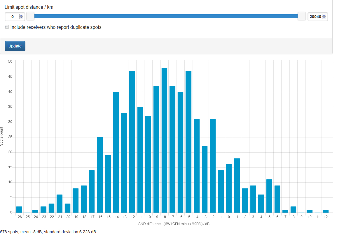
On 12m, it was again like using a beam, and the directionality was significantly sharper, with the strongest SNR reports falling in a very narrow 'corridor', which you can easily extract from the plot below.  

When I cross-checked with the 3-ele back home, the 12m band was clearly in quite poor shape, and so the results I got from the beach do seem to represent a very significant improvement on the Yagi, perhaps equivalent to a 5 element or more.  I even made a number of DX QSOs as far as Western Siberia from the beach.  From home, all my 'CQ' calls went unanswered, and the only two signals I could hear were very much weaker than at the beach:

12m results, FT8

In carting a load of stuff to the beach, I forgot the antenna analyser.  Even so, the approximate SWR figures, as given by the transceiver, were as follows (at the end of 300 Ohm twin and a 4:1 balun).  Remember that, with twin wire, line losses at even very high SWR are negligible, at only a small fraction of a dB.  All these bands matched easily and quickly with the TS480's internal tuner:

160m: 3:1

80m: 1.3:1

60m: didn't measure!

40m: 1.3:1

30m: 1:1

20m: 1.7:1

17m: 3:1

15m: 1:1

12m: 1.3:1 

10m: 1.7:1

6m: 1.4:1


So, is this an antenna worth continuing tests with?  After some thought, I concluded that it is - even though most texts give a terminated rhombic an efficiency of somewhat less than 50% (but this isn't really a good way to judge an antenna, especially down at the beach). 

Firstly, it's a true single-wire, all-band antenna.  It probably doesn't give a super-effective signal out on the lower bands, but then, it's always better than not having any access to those bands.  Receive on those bands seems to be exceptionally good, subject to further testing.

Secondly, it is easy to put up.  The most difficult thing is getting a sturdy enough support for your central pole.  I used, for the first time this outing, a 90-degree angle iron hammered into the ground (with wood, to avoid mushrooming the metal), which went into the ground very easily, and gave more than adequate support for stong winds.  I plan to weld small side steps so that I can simply stand on it to drive it into the ground, rather than hammer it.

Very simple, cheap 10m pole support.  90 -degree steel, with a sharp spike cut into the bottom.


Thirdly, the antenna will tolerate high winds easily when the wind is perpendicular to the wire beaming direction.  When it is along the wire direction, the central support will bend a lot, and stress the upwind wire.  This is not a problem, so long as you use something like kevlar-cored wire, which can take the load easily.

Finally, the first, admittedly not very complete testing shows that, especially from 17m up, this is likely to be a very good, directional antenna, especially when used near watery situations.

The next step is to make a version with its focus on the 14MHz band.  That will make comparisons with past data, and new data yet to be gathered, much simpler.  Wire is already on order!

Again, it was very nice to be approached by a number of people, interested to know what I was doing.  I even seem to have informed them in a way they liked!  Meanwhile, the UK's newest polar research vessel 'Boaty McBoatface' (actually the Sir David Attenborough), was undergoing its first sea trials just offshore from my antenna!

The RRS Sir David Attenborough, named in a popular vote as 'Boaty McBoatface', leaving Liverpool some days ago for the Irish Sea trials.