Sunday, 2 December 2012

WSPR Around The World.

WSPR is one of those things that I kept coming across, but knew little about.  In fact, I had no idea other than it was some kind of beacon mode, and I knew nothing about those, either.

Then, one day, the penny dropped.  I was looking into JT65, another weak signal digital mode, and then came across WSPR in the same software package known as WSJT.  For WSPR, though, I use the standalone package for that mode, known simply as WSPR (free).

Screen shot, showing WSPR signal waterfall.

The main problem at this station for some time has been the lack of a proper digital interface.  I decided last week that enough was enough, and took the plunge with Neil, G4ZLP's USB interface, which really is hand made, and got me running on all the digital modes in less than 25 minutes from opening the box and having no previous digital experience at all.

The only problem I did come across was signal stability, which is very demanding for digital modes - just +/- 1Hz is the ideal, and beyond 4Hz, the software will struggle to decode the signal.  My TS480 is pretty stable, but only if it doesn't run too hot or cold; it needs to settle down into an undemanding routine of sending some, listening more (which is how WSPR is meant to work, anyway).  It's changes in the crystal temperature that are the problem, not which temperature it's at per se.  Too much on and offing of the cooling fan introduces big swings in the stability of the reference crystal; I won't be forking out even more money for a temperature-compensated one, which is anyway not perfect.  In practice, swings of +/-3Hz don't seem to affect the received coverage much, but I now have it down to about -1Hz, which is more than acceptable, given the equipment.

Getting out on 20 metres and above is no problem; a multiband, 4:1-fed delta loop cut nominally for 20m works a treat.  But 30 and more especially 40m were not so good, as I had to rely on an end-fed vertical that struggled to get out well on low power, and it is a very noisy antenna on 40m.

The spark of inspiration then hit me.  All those hours of reading antenna literature paid off.  If I can't and don't want to put up a 20m-long dipole for 40m, why not put up a half-delta loop?  This is just 1/6 wave high - an old and partly broken fishing/crappie/squid pole does the job for me - and 1/3 wave as a sloping horizontal section to the ground.  The antenna is grounded into copper water pipe sections driven into our superb ground, fed with coax into a balun or other common-mode busting device.
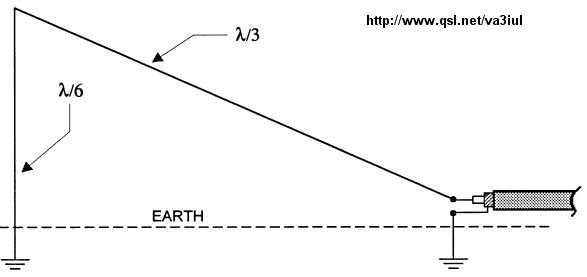
That's all there is too it.  Earth connections are to copper pipes or rods that provides the other half of the antenna, but use a 1:1 balun or ferrites for the coax!

We all know about antenna images, but it all seems somehow unlikely, somehow unreal.  But I can tell you that reality proves the theory!  Within a few minutes, my 4W signal was reaching Australia during the evening - something I could only dream about with my vertical on 40m.  The noise level for the band has crashed, and now I can clearly hear real 40m SSB DX signals from antipodean points.  Over the next few days, I'll try to talk to them, as well!

So there you go.  Full delta loop performance, with low-angle DX pattern for 40m (matches up on higher bands, too), for half the wire, half the space, and no stupidly-tall vertical structures to contend with.  Who couldn't do with an antenna like that?

Monday, 19 November 2012

Which HF Antenna Should I Get?

Don't worry!  This is not going to be a post about whether a 3 element yagi is better than a hexbeam or some typical drivel.

In fact, it's a headline aimed at getting some search engine hits so that beginners can read this, a second update, celebrating my first complete year of relatively casual operating, showing just how much can be achieved without splashing-out on expensive ham equipment. 

Regular readers may recall I bought my first rig off E-Bay, costing me a modest £270 for a very nicely kept Kenwood TS-50 that is still fully functional.  I've since bought a TS-480SAT.

£270 got me this excellent rig to start off my ham career.  It's still working strong.
 
My first antenna for about two months was just a long piece of copper wire strung from the ATU's 'wire' output, out through the wall, up 5m and then sloping down to the bottom of one corner of our garden - about 23 metres of wire, chosen for no particular reason.

I could only run 50W out of that antenna due to the difficulty in matching it due to wild impedance changes.  On a few occasions, I got some hefty RF burns to my PTT finger, but they weren't things that hurt for any more than a minute or two!


Despite all this, I still got out daily to the Caribbean, the US, all of Europe and even once into VK.   A very poor antenna system, but the thrill of making it to VK-land with that wire is an excitement that was very much relished!

Can't do real DX with simple equipment?  Rubbish!  An indicative map of my first year's operating with 100W SSB and a delta loop antenna.
 
Big guns will say 'yeah, but your signal was rubbish!'.  Well, not that bad, as I hit the back of the VK's beam at the time!  And it misses - completely - the raw excitement of making that far-off contact when you've never done if before.  Filling you logbook every time you press a button is, perhaps, not quite so satisfying.

Since then, I discovered the joy of delta loops - and loops in general.  I use full wave loops in various shapes from 20m HF operating to 70cm satellite downlink, and they are very easy-to-match antennas.  I can't see that I will be moving to anything else any time soon, although my elevated, sloping ground and rural location does maximise the performance.

What were the highlights of the 2011-2012 operating year for me?  Often, they were not long-haul DX, although getting into Antarctica was certainly an exception!  After all, the bloke on the other end doesn't think he is very exciting for being where he is.  He's just 'there', whilst I am 'here'.

No, the memorable ones are made special for their humanity and for transporting my imagination to another place.  A man talking to me yesterday on 10m through his 5W handheld into the KQ2H repeater in New York, out with his dog in Central Park. 

I painted much the same mental image when I had a QSO with a VK/mobile station.

Then there was the VK mobile station, where I could clearly hear the dusty road and engine noise as he thundered across the vast Australian outback to his home, about 2 days distant.

A maritime mobile station in port in Brazil - and hearing the same OM off Sierra Leone and then Australia.

An elderly, wheelchair-bound man in Ukraine, saying he never saw anyone and wouldn't know what to do with himself if it were not for amateur radio.  I often think about that man.

A contact on an otherwise-empty 15m band with a Peruvian station, special as it's where my eldest daughter lives.

Finally, a Spanish station honking his horn, saying, "You see?  Real mobile, eh?"

Cheers!  How HK3C imagined me!

They all made me smile, as did the esteemed HK3C - John Bartlett's exchange with me just before last Christmas, when he created in his mind a picture of me sitting with velvet slippers and a dressing gown as I sipped some Ruby Port at the operating chair!   Not far off, John.  Not far off at all...


So, all I will say to those, like me, who have held back from either getting into transmitting, or becoming an operator at all, is: get hold of a delta loop!  I do keep banging-on about this, but there are very good reasons why.  Here they are again:

(1) Cheap.  You can make one out of any junk wire, and so long as you can use a tape measure and cut some wire (about my level of expertise last year), you can't realistically go wrong. You can even buy a delta for a price less than the wire and a good balun if you don't want to homebrew.

(2) Forgiving.  My 20m loop was 1.5m too long for many months.  It still allowed me to operate the world on SSB, even though the effectiveness of the antenna was clearly compromised to a considerable degree. I only kept it at that length because it was working pretty well and adjusting things tends to cause headaches.  It now sings perfectly on 20m after a few hours of careful adjustment.

(3) In all but the worst environmental conditions (powerline clutter, very hemmed-in situations, etc), delta loop wire lengths are very good at conforming to theoretical predictions.  Use the variety of online calculators and cross-check their output (be sure they are actually different sources, too!) rather than books, as I've found a lot of errors on wire lengths, often ones which have been repeated for years, in many of those!

(4) Simple to erect.  You need just one fishing pole to get a delta for the 20m - 6m bands up into the air, with a base height of about 1.5-2m.  This makes it good for rapid, stealthy deployment.  If you have trees, a delta becomes essentially invisible.  Getting a dipole to 10m, if you have no trees or existing supports, is very much harder and more visible.

(5) You can feed with either a 4:1 balun and 50 Ohm coax at the antenna, or with twin feed to an ATU's internal 4:1.  I suggest you use good quality 4:1 external baluns, such as those made by hand by G-Whip.

(6) An excellent low-angle radiator.  On the excellent mineralised ground here, the peak gain is at 12-15 degrees and essentially the same value - about 2.05dBi - as that of a dipole (typically 2.15dBi), but with an omnidirectional pattern that falls only by about 2dB in the worst direction (in the plane of the antenna wire).

(7) Makes an excellent, easy-to-deploy portable antenna.

So, ignore the adverts, the wildly over-optimistic adverts about no radials and true aircraft alloys.  Just get some wire and start making your own antennas.  Then, start talking to the world!

Happy Christmas for 2012, and have a Great 2013!


Friday, 16 November 2012

Wire Length for 20m Delta Loops

An update on the delta loop is overdue.  I love these antennas.  They turned amateur radio from a noisy, poor signal sort of hobby into one where I could enjoy global DX for essentially no cost.

I've had my moans about how difficult it is to find reliable information on getting a delta to resonance, and I still don't understand why so many different views, because deltas are not especially sensitive to their environment.

Sometimes, you just have to use one of these.  Just not too much!

Anyhow, I decided to go out and do a proper job of getting my delta to sing properly today.  No wind, and a warmish winter day helped.  I disconnected the coax, attached an SWR meter to my old TS-50 running on a car battery, and then hooked up with a short piece of coax to the 4:1.  The whole set-up, radio and all, remember, was outside, working at the antenna itself, with no more than about 1.5m of coax in the connections.

As it was, I knew the antenna was too long.  This was because I stupidly tried, being a bit green behind the ears a year ago, to tune the antenna using the ATU.  This is a very dumb idea for two reasons: meters on ATUs seem not to be so good on cheaper models, and measuring the SWR at the transceiver, rather than antenna end makes the SWR look better than it is because of losses in the coax.

So, a year wiser, I sent a signal into the delta.  The meter read 3:1 at the upper end of 20m, 2.5:1 at the lower end: the loop was, as I knew, too long.  Although it's obvious what I had to do next, you always have that feeling that, when you chop wire, at some point, you'll end up regretting it.  Antennas don't play ball and slowly drop to a good SWR like they're meant to.  They often stop at some value well short of 1:1, and then start climbing.

After a good old chop that brought me back to a piece of tape on the wire I'd marked the theoretically-correct length a year ago - 21.3m - I found the SWR was beginning to bottom-out at 1.6 to 1.7:1.  That's good enough for me, and I expect it would not go much lower, if any with further chops, especially as the 4:1 balun almost certainly brings the system impedance down below 50 Ohms.

Coming back indoors, I found the match at the transceiver end almost perfect, needing no ATU to work 20m and with a near-full 100W going out.

Job done.  I hope!

Friday, 9 November 2012

Delta Loop in the Wind!

Over the past year, I've been exposing my fishing-pole supported delta loop for 20m to increasingly harsh conditions.

Whilst putting the pole up and down is very easy, taking only a minute, it is a bit of a hassle, especially as in the UK, winds tend to blow up, die down, and blow up again over the course of a day.  Constant retraction in the face of high winds is therefore not really ideal.


video-2012-11-02-13-16-48 from John Rowlands on Vimeo.

My pole has never slipped under load.  Slippage happens when the pole is exposed to winds from another direction, because they've already been loosened, and so fall down.  The trick is to stop the sections slipping, which most people do with tape.  This is OK, but it does damage the protective lacquer on the pole, which does have a certain degree of weather protecting quality to it.

Now I use jubilee clips (hose clamps) with butterfly nuts at the bottom of each section.  I got mine in the UK from FEP Hydraulics.  This seems to work very well, in that my antenna has now lived through several strong gales (up to 55mph) from the west and east, with no slippage.


Friday, 2 November 2012

SteppIR vs. Delta Loop - Who's The Best?

It's been windy again this week.  But I'm getting more confident in my fishing pole-and-wire 20m delta loop's ability to put up with hurricane-force winds (a term I use accurately - we have 120km/h or more regularly throughout the winter - and sometimes the summer!)

A wire triangle can't possibly be as good as a beam running power, right?  Wrong!

So, I switched on to find an US east-coast station coming in at a nice 58 or so.  He had a straightforward three element tribander on top of a house chimney, running 600W.

One of my colleagues down in Swansea, meanwhile, called said US station.  He was reported as received at 55.  He was running a three (I think!) element SteppIR antenna, with 400W going out from 40 feet.  Most of us would agree that's a big investment and an excellent set up.  What it doesn't tell you about is the antenna's environment.  Swansea is a highly-developed, urban environment.  My QTH isn't.

A big, expensive antenna does not automatically buy the best signal.

So, I fired a call across to the same US station.  Remember: my antenna is a pocket-money one element delta loop held aloft by a 10m fishing pole with the top 2m removed to allow weight to be carried at the tip.  I was running 100W, probably more like 90W after losses.

Who do you think had the best signal?

Well, it was neck-and-neck: the multi-thousand dollar SteppIR, amp and tower set up was getting the same report as my pocket money delta!

I wouldn't be so stupid as to claim my set up would win in every comparison with the more expensive system, but you do have to accept that bigger, more expensive and more powerful does not automatically mean a better received signal.

Environment is important, perhaps more so than many will accept.  Think about it.  If you want good low angle departure angles for long-haul DX, you need a horizon that is so clear of obstructions that very few living in countries like the UK will ever have that luxury.  Few live within sight of the sea.  Or have high concentrations of metals in the ground beneath their antennas.  We have all of these things, which makes a big difference to how well a simple station can get out.

So before you spend the bucks.  Try simple, proven antennas, especially verticals (which includes vertical dipoles, of course), to see just how far and how well you can reach...


Saturday, 27 October 2012

Bi-Square Loop - Fun All The Way on 10m

Yes folks, it's autumn in full swing, as is the 10m band!

For the past week or so, conditions on 10m have been outstanding.  Of particular interest to me is the excellent signal coming across from the Big Apple from KQ2H, a repeater that was once located on one of the ill-fated World Trade Centre buildings.

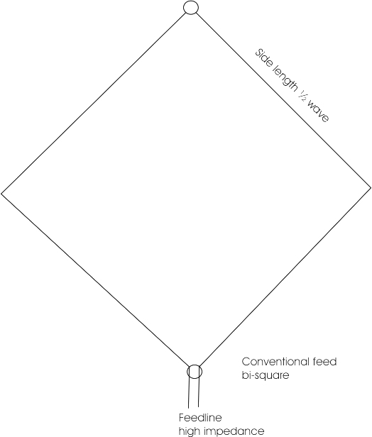
The bi-square in action.  An 8m-fishing pole supports the top.  Remember that this is not actually a loop - it's open at the top!
And by 'excellent', I am not exaggerating; the signal for hours on end swings to full-scale deflection on the signal strength meter - that's 59+60dB on my rig!

Of course, that's just the repeater's signal; the signal you get into it depends on the usual parameters.

But conditions are not always this good on 10m, and it can be expected that, come the end of this sunspot cycle's peak, the band will be mostly dead.  That makes big investment in a 10m antenna a poor investment choice.

A bi-square, correctly depicted - unlike many other internet resources - as two wires, open at the top.  It is NOT a closed loop!


Enter the 10m bi-square loop wire antenna.  I first came across this truly amazing antenna in 'The International Antenna Collection' book, which compares it against a yagi, highlighting some interesting and often conveniently overlooked points.

Remarkably, this most basic of wire antennas - it is just a loop, open at the top (so not a loop at all!) with both sides pulled out into a diamond shape, each 'leg' being a full wavelength long.  It's fed with twin at the bottom; I use 300Ohm ribbon, to an ATU which makes matching very easy (but do look out for strange effects with twin - keep it well away from other conductive materials.

I once asked a modelling question about the bi-square, and for the record, I reproduce below (in orange) the kindly WB6BYU came up with the following analysis, and interesting points.  I don't disagree with him about full wave loops, but I can say the bi-square has performed admirably from here, often making me the subject of mini-pile ups on KQ2H - all with just 100W, which gets boosted, as a minimum, to about 380W in effective radiated power.  At optimal configuration, this can be as high as 560W EIRP. 

Another useful thing about this antenna is that, if you open it at the bottom and connect one wire to one pole of a 4:1 balun, and a 1m-long counterpoise to the other pole (the other leg remains free), you get a very useful 2-element vertical beam for 20m (see Les Moxon's 'HF Antennas for All Locations').

'OK, I ran some models in EZNEC.  Starting with a 15m Bi-Square loop with the top at 11m.
and the bottom about 1m above ground.  I rounded the dimensions to make it easier to
vary the model.  Then I progressively squashed the loop, keeping the bottom 1m off the
ground, and recorded the gain and vertical angle of maximum radiation:

11m   8.6dBi @ 28 degrees
9m    7.8dBi @ 34 degrees
7m    6.9dBi @ 45 degrees

The vertical angle of radiation increases significantly.  Height is important for low angle
radiation.  In the process the feedpoint impedance dropped from about 3000 ohms at
resonance to 1400 ohms.

Now let's see what happens if we raise the bottom of the antenna rather than
lowering the top (while leaving the top at 11m.)

1m   8.6dBi @ 28 degrees
3m   9.2dBi @ 28 degrees
5m   9.6dBi @ 25 degrees

Clearly the higher average height above ground improves antenna performance, even
though the loop is more squashed.

Now, for comparison, let's look at just the top wires, so a sloping "Two Half Waves
In Phase."

6.7dBi @ 23 degrees

If we use a standard inverted vee at the same height (11m) then we get:

6.8dBi @ 19 degrees

For comparison, let's go back to the original Bi-Square and compare the radiation at
these vertical angles:

8.3dBi @ 23 degrees
7.7dBi @ 19 degrees

And we can check a full wave loop with a top height of 11m at the same angles:

7.6dBi @ 28 degrees
8.1dBi @ 22 degrees (maximum)
7.9dBi @ 19 degrees

So while the Bi-Square loop has a higher peak gain, the standard full wave loop has equal
or better gain at lower elevation angles.

Let's see what happens when we lower it:

9m  7.1dBi @ 28 degrees
7m  5.7dBi @ 39 degrees

(This is without squashing the full wave loop, which would raise the average radiation height.)

While the Bi-Square may be fun to experiment with (and should give a good match to 50 ohms
using the common window twinlead that is around 400 ohms impedance as long as the antenna
is square), I'm not sure there is a lot of benefit to using one at low height compared to a full
wave loop, or possibly even a dipole or inverted vee with the same top height, especially if
your primary objective is DX.'


Saturday, 13 October 2012

Satellite Working - Cheap Style!

Some months ago, I started taking an interest in working satellites on FM.  I built a lovely 2m, 5-element quad, which shows very strong gain and even stronger directionality.  It quickly came into very useful service for remote repeaters (up to 158 miles so far on 1.8W!) and for more local work.

But that's where satellite progress stopped.  Always too busy with one thing or another.

So, with clear autumn skies telling me to get a move on and make my 70cm downlink antenna, I went to see what junk I had to cobble together.

I like quads, so my 70cm antenna is a 7-element quad, built with one supporting arm per element because at 70cm, when using hard drawn copper, the elements are mostly self-supporting.   I used standard online calculators, which don't always give good results, to guide my wire and spacing lengths, and, for once, this did yield a good antenna.

The completed 70cm, 7 element quad.  Works a treat, even if it looks a bit rough!

The boom is just 25mm x 25mm pine, with lightweight timber square section spreaders, all heavily varnished for the weather.  If you are building one, use moderately smaller section boom timber, as this one proved a bit too heavy for comfort, especially if operating two antennas at the same time!

Connection is just a short length - about 60cm in this case - of junk RG58/U, which has very minimal losses over such a distance, connected directly via spade connectors at the driven element.  There's no need for a balun or matching section, especially as this is just a receiving antenna for this purpose.

Does it work?  Yep!  I wondered why, with 10+dBi gain, I wasn't hitting one of the toneburst-activated 70cm repeaters even when directly underneath is.  Thiss seems to be a problem with the stability and tolerance of the 1750Hz tone, now rarely used due to CTCSS taking over, on my very cheap, but otherwise very good, Chinese handheld.  Using a pure tone did access it, even from inside the house.

And on satellites?  Excellent!  Easily picks up SO-50 as soon as it hints at coming over the horizon, with very clear, stable signals at about S 6 across the vast majority of the pass (SO-50 transmits with only 250mW at launch).

Very pleased indeed!  Total cost: about £6 in all new materials.  Essentially nothing if you have bits lying around. Just remember to make it as lightweight as possible.

Update: I made my first sat QSO with EA7HZZ using the antenna for downlink.  I used just 4W into the 5 element 2m uplink quad.  Not bad!  I'm now making plenty of contacts on each pass.

Next step: Operating two separate antennas is too cumbersome, so I'm going to build one of these tape measure antennas, again at next-to-nothing cost.  I'll mount the quads on a motorised mount some day.

An example of a 2m tape measure sat beam.  This gets the signal up fairly well, but the 70cm receive antenna is too weak for SO-50 unless it has an unfeasible number of elements.

Update on the next step!  I built a lovely 2-band tape measure antenna for higher elevation passes, and managed to get a very good match on both.  But, and as is my experience with quads vs. yagis, the yagi is very much poorer in performance than the quads. The yagis are also much, much harder to get to the right resonance and match than quads.  All that said, I have managed good QSOs into SO-50, showing the 2m yagi is adequate at 3 elements, but it is rare that I can hear my voice clearly coming back, though others seem to hear me fine.  That, then, must be down to the 70cm antenna's gain - I have no such difficulty at all with the 7-ele quad for 70cm.  I really can't say it was worth making this antenna because of the fiddly matching and performance issues, and that a non-elevated quad system works very well for most passes.