Over the past year, I've been exposing my fishing-pole supported delta loop for 20m to increasingly harsh conditions.
Whilst putting the pole up and down is very easy, taking only a minute, it is a bit of a hassle, especially as in the UK, winds tend to blow up, die down, and blow up again over the course of a day. Constant retraction in the face of high winds is therefore not really ideal.
video-2012-11-02-13-16-48 from John Rowlands on Vimeo.
My pole has never slipped under load. Slippage happens when the pole is exposed to winds from another direction, because they've already been loosened, and so fall down. The trick is to stop the sections slipping, which most people do with tape. This is OK, but it does damage the protective lacquer on the pole, which does have a certain degree of weather protecting quality to it.
Now I use jubilee clips (hose clamps) with butterfly nuts at the bottom of each section. I got mine in the UK from FEP Hydraulics. This seems to work very well, in that my antenna has now lived through several strong gales (up to 55mph) from the west and east, with no slippage.
Friday, 9 November 2012

Friday, 2 November 2012
SteppIR vs. Delta Loop - Who's The Best?
It's been windy again this week. But I'm getting more confident in my fishing pole-and-wire 20m delta loop's ability to put up with hurricane-force winds (a term I use accurately - we have 120km/h or more regularly throughout the winter - and sometimes the summer!)
So, I switched on to find an US east-coast station coming in at a nice 58 or so. He had a straightforward three element tribander on top of a house chimney, running 600W.
One of my colleagues down in Swansea, meanwhile, called said US station. He was reported as received at 55. He was running a three (I think!) element SteppIR antenna, with 400W going out from 40 feet. Most of us would agree that's a big investment and an excellent set up. What it doesn't tell you about is the antenna's environment. Swansea is a highly-developed, urban environment. My QTH isn't.
So, I fired a call across to the same US station. Remember: my antenna is a pocket-money one element delta loop held aloft by a 10m fishing pole with the top 2m removed to allow weight to be carried at the tip. I was running 100W, probably more like 90W after losses.
Who do you think had the best signal?
Well, it was neck-and-neck: the multi-thousand dollar SteppIR, amp and tower set up was getting the same report as my pocket money delta!
I wouldn't be so stupid as to claim my set up would win in every comparison with the more expensive system, but you do have to accept that bigger, more expensive and more powerful does not automatically mean a better received signal.
Environment is important, perhaps more so than many will accept. Think about it. If you want good low angle departure angles for long-haul DX, you need a horizon that is so clear of obstructions that very few living in countries like the UK will ever have that luxury. Few live within sight of the sea. Or have high concentrations of metals in the ground beneath their antennas. We have all of these things, which makes a big difference to how well a simple station can get out.
So before you spend the bucks. Try simple, proven antennas, especially verticals (which includes vertical dipoles, of course), to see just how far and how well you can reach...
 |
| A wire triangle can't possibly be as good as a beam running power, right? Wrong! |
So, I switched on to find an US east-coast station coming in at a nice 58 or so. He had a straightforward three element tribander on top of a house chimney, running 600W.
One of my colleagues down in Swansea, meanwhile, called said US station. He was reported as received at 55. He was running a three (I think!) element SteppIR antenna, with 400W going out from 40 feet. Most of us would agree that's a big investment and an excellent set up. What it doesn't tell you about is the antenna's environment. Swansea is a highly-developed, urban environment. My QTH isn't.
 |
| A big, expensive antenna does not automatically buy the best signal. |
So, I fired a call across to the same US station. Remember: my antenna is a pocket-money one element delta loop held aloft by a 10m fishing pole with the top 2m removed to allow weight to be carried at the tip. I was running 100W, probably more like 90W after losses.
Who do you think had the best signal?
Well, it was neck-and-neck: the multi-thousand dollar SteppIR, amp and tower set up was getting the same report as my pocket money delta!
I wouldn't be so stupid as to claim my set up would win in every comparison with the more expensive system, but you do have to accept that bigger, more expensive and more powerful does not automatically mean a better received signal.
Environment is important, perhaps more so than many will accept. Think about it. If you want good low angle departure angles for long-haul DX, you need a horizon that is so clear of obstructions that very few living in countries like the UK will ever have that luxury. Few live within sight of the sea. Or have high concentrations of metals in the ground beneath their antennas. We have all of these things, which makes a big difference to how well a simple station can get out.
So before you spend the bucks. Try simple, proven antennas, especially verticals (which includes vertical dipoles, of course), to see just how far and how well you can reach...
Saturday, 27 October 2012
Bi-Square Loop - Fun All The Way on 10m
Yes folks, it's autumn in full swing, as is the 10m band!
For the past week or so, conditions on 10m have been outstanding. Of particular interest to me is the excellent signal coming across from the Big Apple from KQ2H, a repeater that was once located on one of the ill-fated World Trade Centre buildings.
And by 'excellent', I am not exaggerating; the signal for hours on end swings to full-scale deflection on the signal strength meter - that's 59+60dB on my rig!
Of course, that's just the repeater's signal; the signal you get into it depends on the usual parameters.
But conditions are not always this good on 10m, and it can be expected that, come the end of this sunspot cycle's peak, the band will be mostly dead. That makes big investment in a 10m antenna a poor investment choice.
Enter the 10m bi-square loop wire antenna. I first came across this truly amazing antenna in 'The International Antenna Collection' book, which compares it against a yagi, highlighting some interesting and often conveniently overlooked points.
Remarkably, this most basic of wire antennas - it is just a loop, open at the top (so not a loop at all!) with both sides pulled out into a diamond shape, each 'leg' being a full wavelength long. It's fed with twin at the bottom; I use 300Ohm ribbon, to an ATU which makes matching very easy (but do look out for strange effects with twin - keep it well away from other conductive materials.
I once asked a modelling question about the bi-square, and for the record, I reproduce below (in orange) the kindly WB6BYU came up with the following analysis, and interesting points. I don't disagree with him about full wave loops, but I can say the bi-square has performed admirably from here, often making me the subject of mini-pile ups on KQ2H - all with just 100W, which gets boosted, as a minimum, to about 380W in effective radiated power. At optimal configuration, this can be as high as 560W EIRP.
Another useful thing about this antenna is that, if you open it at the bottom and connect one wire to one pole of a 4:1 balun, and a 1m-long counterpoise to the other pole (the other leg remains free), you get a very useful 2-element vertical beam for 20m (see Les Moxon's 'HF Antennas for All Locations').
'OK, I ran some models in EZNEC. Starting with a 15m Bi-Square loop with the top at 11m.
and the bottom about 1m above ground. I rounded the dimensions to make it easier to
vary the model. Then I progressively squashed the loop, keeping the bottom 1m off the
ground, and recorded the gain and vertical angle of maximum radiation:
11m 8.6dBi @ 28 degrees
9m 7.8dBi @ 34 degrees
7m 6.9dBi @ 45 degrees
The vertical angle of radiation increases significantly. Height is important for low angle
radiation. In the process the feedpoint impedance dropped from about 3000 ohms at
resonance to 1400 ohms.
Now let's see what happens if we raise the bottom of the antenna rather than
lowering the top (while leaving the top at 11m.)
1m 8.6dBi @ 28 degrees
3m 9.2dBi @ 28 degrees
5m 9.6dBi @ 25 degrees
Clearly the higher average height above ground improves antenna performance, even
though the loop is more squashed.
Now, for comparison, let's look at just the top wires, so a sloping "Two Half Waves
In Phase."
6.7dBi @ 23 degrees
If we use a standard inverted vee at the same height (11m) then we get:
6.8dBi @ 19 degrees
For comparison, let's go back to the original Bi-Square and compare the radiation at
these vertical angles:
8.3dBi @ 23 degrees
7.7dBi @ 19 degrees
And we can check a full wave loop with a top height of 11m at the same angles:
7.6dBi @ 28 degrees
8.1dBi @ 22 degrees (maximum)
7.9dBi @ 19 degrees
So while the Bi-Square loop has a higher peak gain, the standard full wave loop has equal
or better gain at lower elevation angles.
Let's see what happens when we lower it:
9m 7.1dBi @ 28 degrees
7m 5.7dBi @ 39 degrees
(This is without squashing the full wave loop, which would raise the average radiation height.)
While the Bi-Square may be fun to experiment with (and should give a good match to 50 ohms
using the common window twinlead that is around 400 ohms impedance as long as the antenna
is square), I'm not sure there is a lot of benefit to using one at low height compared to a full
wave loop, or possibly even a dipole or inverted vee with the same top height, especially if
your primary objective is DX.'
For the past week or so, conditions on 10m have been outstanding. Of particular interest to me is the excellent signal coming across from the Big Apple from KQ2H, a repeater that was once located on one of the ill-fated World Trade Centre buildings.
 |
| The bi-square in action. An 8m-fishing pole supports the top. Remember that this is not actually a loop - it's open at the top! |
Of course, that's just the repeater's signal; the signal you get into it depends on the usual parameters.
But conditions are not always this good on 10m, and it can be expected that, come the end of this sunspot cycle's peak, the band will be mostly dead. That makes big investment in a 10m antenna a poor investment choice.
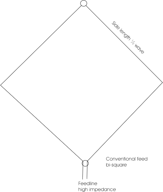 |
| A bi-square, correctly depicted - unlike many other internet resources - as two wires, open at the top. It is NOT a closed loop! |
Enter the 10m bi-square loop wire antenna. I first came across this truly amazing antenna in 'The International Antenna Collection' book, which compares it against a yagi, highlighting some interesting and often conveniently overlooked points.
Remarkably, this most basic of wire antennas - it is just a loop, open at the top (so not a loop at all!) with both sides pulled out into a diamond shape, each 'leg' being a full wavelength long. It's fed with twin at the bottom; I use 300Ohm ribbon, to an ATU which makes matching very easy (but do look out for strange effects with twin - keep it well away from other conductive materials.
I once asked a modelling question about the bi-square, and for the record, I reproduce below (in orange) the kindly WB6BYU came up with the following analysis, and interesting points. I don't disagree with him about full wave loops, but I can say the bi-square has performed admirably from here, often making me the subject of mini-pile ups on KQ2H - all with just 100W, which gets boosted, as a minimum, to about 380W in effective radiated power. At optimal configuration, this can be as high as 560W EIRP.
Another useful thing about this antenna is that, if you open it at the bottom and connect one wire to one pole of a 4:1 balun, and a 1m-long counterpoise to the other pole (the other leg remains free), you get a very useful 2-element vertical beam for 20m (see Les Moxon's 'HF Antennas for All Locations').
'OK, I ran some models in EZNEC. Starting with a 15m Bi-Square loop with the top at 11m.
and the bottom about 1m above ground. I rounded the dimensions to make it easier to
vary the model. Then I progressively squashed the loop, keeping the bottom 1m off the
ground, and recorded the gain and vertical angle of maximum radiation:
11m 8.6dBi @ 28 degrees
9m 7.8dBi @ 34 degrees
7m 6.9dBi @ 45 degrees
The vertical angle of radiation increases significantly. Height is important for low angle
radiation. In the process the feedpoint impedance dropped from about 3000 ohms at
resonance to 1400 ohms.
Now let's see what happens if we raise the bottom of the antenna rather than
lowering the top (while leaving the top at 11m.)
1m 8.6dBi @ 28 degrees
3m 9.2dBi @ 28 degrees
5m 9.6dBi @ 25 degrees
Clearly the higher average height above ground improves antenna performance, even
though the loop is more squashed.
Now, for comparison, let's look at just the top wires, so a sloping "Two Half Waves
In Phase."
6.7dBi @ 23 degrees
If we use a standard inverted vee at the same height (11m) then we get:
6.8dBi @ 19 degrees
For comparison, let's go back to the original Bi-Square and compare the radiation at
these vertical angles:
8.3dBi @ 23 degrees
7.7dBi @ 19 degrees
And we can check a full wave loop with a top height of 11m at the same angles:
7.6dBi @ 28 degrees
8.1dBi @ 22 degrees (maximum)
7.9dBi @ 19 degrees
So while the Bi-Square loop has a higher peak gain, the standard full wave loop has equal
or better gain at lower elevation angles.
Let's see what happens when we lower it:
9m 7.1dBi @ 28 degrees
7m 5.7dBi @ 39 degrees
(This is without squashing the full wave loop, which would raise the average radiation height.)
While the Bi-Square may be fun to experiment with (and should give a good match to 50 ohms
using the common window twinlead that is around 400 ohms impedance as long as the antenna
is square), I'm not sure there is a lot of benefit to using one at low height compared to a full
wave loop, or possibly even a dipole or inverted vee with the same top height, especially if
your primary objective is DX.'
Saturday, 13 October 2012
Satellite Working - Cheap Style!
Some months ago, I started taking an interest in working satellites on FM. I built a lovely 2m, 5-element quad, which shows very strong gain and even stronger directionality. It quickly came into very useful service for remote repeaters (up to 158 miles so far on 1.8W!) and for more local work.
But that's where satellite progress stopped. Always too busy with one thing or another.
So, with clear autumn skies telling me to get a move on and make my 70cm downlink antenna, I went to see what junk I had to cobble together.
I like quads, so my 70cm antenna is a 7-element quad, built with one supporting arm per element because at 70cm, when using hard drawn copper, the elements are mostly self-supporting. I used standard online calculators, which don't always give good results, to guide my wire and spacing lengths, and, for once, this did yield a good antenna.
The boom is just 25mm x 25mm pine, with lightweight timber square section spreaders, all heavily varnished for the weather. If you are building one, use moderately smaller section boom timber, as this one proved a bit too heavy for comfort, especially if operating two antennas at the same time!
Connection is just a short length - about 60cm in this case - of junk RG58/U, which has very minimal losses over such a distance, connected directly via spade connectors at the driven element. There's no need for a balun or matching section, especially as this is just a receiving antenna for this purpose.
Does it work? Yep! I wondered why, with 10+dBi gain, I wasn't hitting one of the toneburst-activated 70cm repeaters even when directly underneath is. Thiss seems to be a problem with the stability and tolerance of the 1750Hz tone, now rarely used due to CTCSS taking over, on my very cheap, but otherwise very good, Chinese handheld. Using a pure tone did access it, even from inside the house.
And on satellites? Excellent! Easily picks up SO-50 as soon as it hints at coming over the horizon, with very clear, stable signals at about S 6 across the vast majority of the pass (SO-50 transmits with only 250mW at launch).
Very pleased indeed! Total cost: about £6 in all new materials. Essentially nothing if you have bits lying around. Just remember to make it as lightweight as possible.
Update: I made my first sat QSO with EA7HZZ using the antenna for downlink. I used just 4W into the 5 element 2m uplink quad. Not bad! I'm now making plenty of contacts on each pass.
Next step: Operating two separate antennas is too cumbersome, so I'm going to build one of these tape measure antennas, again at next-to-nothing cost. I'll mount the quads on a motorised mount some day.
Update on the next step! I built a lovely 2-band tape measure antenna for higher elevation passes, and managed to get a very good match on both. But, and as is my experience with quads vs. yagis, the yagi is very much poorer in performance than the quads. The yagis are also much, much harder to get to the right resonance and match than quads. All that said, I have managed good QSOs into SO-50, showing the 2m yagi is adequate at 3 elements, but it is rare that I can hear my voice clearly coming back, though others seem to hear me fine. That, then, must be down to the 70cm antenna's gain - I have no such difficulty at all with the 7-ele quad for 70cm. I really can't say it was worth making this antenna because of the fiddly matching and performance issues, and that a non-elevated quad system works very well for most passes.
But that's where satellite progress stopped. Always too busy with one thing or another.
So, with clear autumn skies telling me to get a move on and make my 70cm downlink antenna, I went to see what junk I had to cobble together.
I like quads, so my 70cm antenna is a 7-element quad, built with one supporting arm per element because at 70cm, when using hard drawn copper, the elements are mostly self-supporting. I used standard online calculators, which don't always give good results, to guide my wire and spacing lengths, and, for once, this did yield a good antenna.
 |
| The completed 70cm, 7 element quad. Works a treat, even if it looks a bit rough! |
The boom is just 25mm x 25mm pine, with lightweight timber square section spreaders, all heavily varnished for the weather. If you are building one, use moderately smaller section boom timber, as this one proved a bit too heavy for comfort, especially if operating two antennas at the same time!
Connection is just a short length - about 60cm in this case - of junk RG58/U, which has very minimal losses over such a distance, connected directly via spade connectors at the driven element. There's no need for a balun or matching section, especially as this is just a receiving antenna for this purpose.
Does it work? Yep! I wondered why, with 10+dBi gain, I wasn't hitting one of the toneburst-activated 70cm repeaters even when directly underneath is. Thiss seems to be a problem with the stability and tolerance of the 1750Hz tone, now rarely used due to CTCSS taking over, on my very cheap, but otherwise very good, Chinese handheld. Using a pure tone did access it, even from inside the house.
And on satellites? Excellent! Easily picks up SO-50 as soon as it hints at coming over the horizon, with very clear, stable signals at about S 6 across the vast majority of the pass (SO-50 transmits with only 250mW at launch).
Very pleased indeed! Total cost: about £6 in all new materials. Essentially nothing if you have bits lying around. Just remember to make it as lightweight as possible.
Update: I made my first sat QSO with EA7HZZ using the antenna for downlink. I used just 4W into the 5 element 2m uplink quad. Not bad! I'm now making plenty of contacts on each pass.
Next step: Operating two separate antennas is too cumbersome, so I'm going to build one of these tape measure antennas, again at next-to-nothing cost. I'll mount the quads on a motorised mount some day.
 |
| An example of a 2m tape measure sat beam. This gets the signal up fairly well, but the 70cm receive antenna is too weak for SO-50 unless it has an unfeasible number of elements. |
Update on the next step! I built a lovely 2-band tape measure antenna for higher elevation passes, and managed to get a very good match on both. But, and as is my experience with quads vs. yagis, the yagi is very much poorer in performance than the quads. The yagis are also much, much harder to get to the right resonance and match than quads. All that said, I have managed good QSOs into SO-50, showing the 2m yagi is adequate at 3 elements, but it is rare that I can hear my voice clearly coming back, though others seem to hear me fine. That, then, must be down to the 70cm antenna's gain - I have no such difficulty at all with the 7-ele quad for 70cm. I really can't say it was worth making this antenna because of the fiddly matching and performance issues, and that a non-elevated quad system works very well for most passes.
Saturday, 29 September 2012
Yagi vs. Delta Shoot Out!
Well, having come up with a lightweight, strong design for a 2-element loaded yagi, up it went, by moonlight, for tests the following early morning.
Now, I was not able to put the beam up at anything like a good height - just 6m, though the ground does slope away sharply in front of it. So what follows isn't an assessment of what the beam could do if it were at greater heights.
I turned the beam towards the long path signals from the Pacific. Running at the other end of our large garden, away from any interaction between them, was my trusty 20m full wave delta loop which uses vertical polarisation.
Luckily, VK3VCE and VK5PAS were in a group that were only too willing to report on the two antennas. The result? The beam was between 1 and 2 S units down on the delta loop. This was confirmed later in the day, when a station on Prince Edward Island also came in 2 S points down.
So, in terms of decibels, that's a beam, at this height, returning 12dB less in and out firepower than a simple delta loop.
Now, again, the beam wasn't being given a fair chance, and it is a centre-loaded, shortened version. BUT! Let's look at this from the perspective of ease of deployment, use, and cost.
The beam is complex to get up into the air. Books and magazines suggest it's easy, which it is if you have lots of money, plenty of room for guy wires, and permission to put a mast of some sort up. For real hams, it's really very difficult; have a look at how wrong it can go if you're not prepared:
Then you need to rotate the beam. This adds considerably to the expense, and necessarily means you'll have to twist your antenna around endlessly to get the best signals.
Then you'll need to make the whole thing windproof at, for 20m antennas, anything from 8-15m high, depending on whether you have any ground reflection sweet spots. For me, with regular gusts to 80mph or more, this is a big ask, or a recipe for endless upping and downing the beam.
Given that my 2-element beam would appear to have to reach at least 10m before it broke even with the delta loop, with an apex at 8m, supported by a single, $15 fishing pole and which resists winds to about 50mph quite happily, the beam loses the competition, hands down so far as my essential check list is concerned.
Now, my QTH does have a clear aspect, is elevated at about 65m around the surrounding land, has some sea views, and has the best terrestrial ground you could hope for. So a delta may not work quite so well from a cluttered environment, where a yagi placed above the neighbourhood would yield real benefits.
Just keep in mind that, whilst a horizontal beam sounds like a good idea, the reality isn't necessarily so.
 |
| A 2-ele beam like mine. Large, and needs to go up high. |
Now, I was not able to put the beam up at anything like a good height - just 6m, though the ground does slope away sharply in front of it. So what follows isn't an assessment of what the beam could do if it were at greater heights.
I turned the beam towards the long path signals from the Pacific. Running at the other end of our large garden, away from any interaction between them, was my trusty 20m full wave delta loop which uses vertical polarisation.
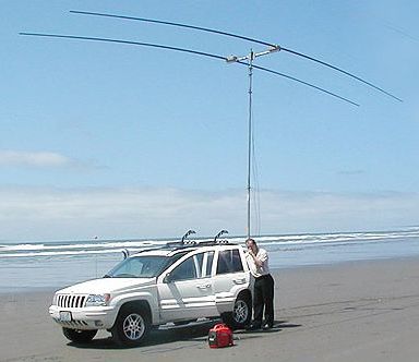 |
| Wow! A SteppIR in a very macho scene. It gives a good impression of the sheer size of even a simple 2-ele beam. But the sad reality is that experienced beach operators will tell you that a simple vertical antenna easily outperforms a yagi from the seaside. So 'beam' doesn't necessarily mean 'best antenna' for all locations. |
Luckily, VK3VCE and VK5PAS were in a group that were only too willing to report on the two antennas. The result? The beam was between 1 and 2 S units down on the delta loop. This was confirmed later in the day, when a station on Prince Edward Island also came in 2 S points down.
 |
| Propped up by an 8m fishing pole and made of any old wire, the delta, with its base at just 1.2m, beat the far more complex beam by anything up to 12dB. |
So, in terms of decibels, that's a beam, at this height, returning 12dB less in and out firepower than a simple delta loop.
Now, again, the beam wasn't being given a fair chance, and it is a centre-loaded, shortened version. BUT! Let's look at this from the perspective of ease of deployment, use, and cost.
The beam is complex to get up into the air. Books and magazines suggest it's easy, which it is if you have lots of money, plenty of room for guy wires, and permission to put a mast of some sort up. For real hams, it's really very difficult; have a look at how wrong it can go if you're not prepared:
Then you need to rotate the beam. This adds considerably to the expense, and necessarily means you'll have to twist your antenna around endlessly to get the best signals.
Then you'll need to make the whole thing windproof at, for 20m antennas, anything from 8-15m high, depending on whether you have any ground reflection sweet spots. For me, with regular gusts to 80mph or more, this is a big ask, or a recipe for endless upping and downing the beam.
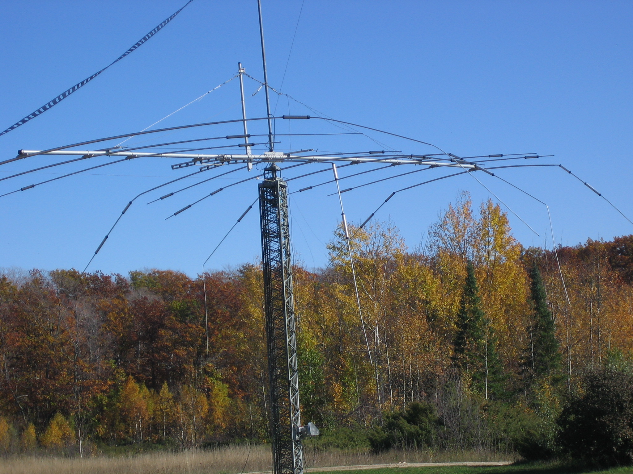 |
| Big antennas can mean big disasters and high repair (or insurance) costs. |
 |
| Low angle patterns typical of low-mounted, vertically polarised deltas. This one's at 5m; at lower base heights, the upper lobe vanishes. Low angle patterns are very useful for DX, and the delta excels in this respect. |
Now, my QTH does have a clear aspect, is elevated at about 65m around the surrounding land, has some sea views, and has the best terrestrial ground you could hope for. So a delta may not work quite so well from a cluttered environment, where a yagi placed above the neighbourhood would yield real benefits.
Just keep in mind that, whilst a horizontal beam sounds like a good idea, the reality isn't necessarily so.
Friday, 21 September 2012
The Compact 20m 2-element Yagi
Living in a windy location, as I always go on endlessly about, makes for a difficult existence as a radio operator.
Over the past few months, and despite the atrocious operating practices often to be found there, the 20m band has become my favourite band for DX. All of this has been with a simple 1-element delta loop for the band, which though simple, is exceptionally effective from this undeveloped hilltop, metal-saturated ground location.
Recently, I decided to pursue a simple 2-element beam for 20m, to see whether the added complexity of getting a beam several metres into the air is worthwhile.
I'd been looking at this easy-to-follow guide for some time, and had long ago built the coils, but never completed the antenna. Inspired by some calm weather, out I went to add some wire and start tuning each element individually, rather than take a chance on the published measurements, build the whole thing and then find it way off resonance!
I also found this guide on a very similar antenna to be excellent and well worth downloading and keeping safe.
Although the peculiarities of the metal saturated ground make this site quite unique, I did find that the element lengths (using kevlar wire) needed to be considerably longer than published, and that's allowing for the fact I wanted my beam mainly for the SSB parts of the band. Kevlar wire is thin strands of copper wound lightly around a kevlar core, and may well behave very differently from flexweave or drawn copper - you'll have to experiment with your own wire preference. The big advantage of kevlar is that it's about three times lighter than flexweave, which is a consideration with saggy fishing poles. The drawback is kevlar's higher cost.
In the end, I found that each half of the dipole, without the coils, needed to be 114.5" (2.91m) long. In other words, the length of each bit of wire either side of each coil (of which there are two per driven element) is 57.25" (1.455m). I did try 3m poles, but they proved too flexible at the ends, so with only a modest penalty if increased weight, I used the upper few sections of an old set of 7m poles, with most of the thinnest, uppermost tip cut away so it doesn't sag. Poles are very cheap at about £7 each from Paul's Angling Supplies (also on Ebay), who have superb service standards.
The reflector is built a bit longer and in accordance with general design patterns for Yagi-Uda antennas - about 5% or so (you can spend all week reading up and chasing different web articles about precisely how long you may want to make it, but you have to start somewhere, so 5% is a good guide!)
The boom is varnished timber, with simple timber just strong and wide enough to accommodate the poles and to tie cable ties around to keep the poles in place (this is by far the lightest, cheapest way, but use quality ties). I'll need to fashion a short stub from timber and plywood to attach the whole thing to the as-yet-unavailable push-up mast, but that's pretty easy.
In theory, the antenna should produce about 4dBd forward gain, with a modest 10dB front-to-back ratio. In other words, if you take a standard rig at 100W and put this antenna at the end of the coax, you'll end up with about 250 watts effective radiated power going off to your target. Signals to the rear will be reduced by about 2 'S' units. Not bad for the price of some wire and fishing poles!
As soon as I get enough money to buy a simple aluminium push-up mast and get the beam at a decent height, I'll let you know whether all the effort is really worthwhile, relative to a simple delta loop propped up with one 8m fishing pole, and which needs no rotator or rotating!
One interesting point to note, well made by my friend John, ZL2JBR, is that you can often find signal 'sweet spots' at certain mounting heights, which you need to find for your location by experimentation (sticking the antenna up at maximum height, then watch your 'S' meter for any changes as you lower it bit by bit). John, for whom I have great respect in understanding radio, reckons that the increase in signal strength can be as dramatic as 10dB. Given John is pretty much the only ZL you will hear on short path most days, and that his antenna is several metres lower than usual theory dictates, his practice certainly matches his ideas! For reasons of reducing mounting difficulties and wind loading, any reduction in height is a welcome thing, believe me.
In the meantime, if you don't want to build a beam, remember that you can make this in the 1-element dipole flavour - a 20m dipole made of super-lightweight fishing poles that's about 40% shorter than a full-sized version, all with very minimal reduction in performance. You can even collapse the poles for stowing out of view, or for taking portable. You should also be able to turn this into a moxon rectangle following some experimentation. Or you could, with stronger supports, fashion some end capacitance hats and shorten the elements further. Plenty to keep you wasting miles of wire, there...
UPDATE:
I found this beam to be a poor performer at 8m. It was 1-2 'S' points down on my 1-element delta loop for 20m. I think the tuning of the elements could have been better, to be honest. That said, it did get across to VK with no problem on long path, but that isn't actually very difficult. Beams are simply too complex for me to bother with at the moment, because of the need to mount them so high and that they catch so much wind. The delta easily wins again!
Over the past few months, and despite the atrocious operating practices often to be found there, the 20m band has become my favourite band for DX. All of this has been with a simple 1-element delta loop for the band, which though simple, is exceptionally effective from this undeveloped hilltop, metal-saturated ground location.
 |
| KA3DRR's lovely 2-element yagi - yours will look much the same. |
Recently, I decided to pursue a simple 2-element beam for 20m, to see whether the added complexity of getting a beam several metres into the air is worthwhile.
I'd been looking at this easy-to-follow guide for some time, and had long ago built the coils, but never completed the antenna. Inspired by some calm weather, out I went to add some wire and start tuning each element individually, rather than take a chance on the published measurements, build the whole thing and then find it way off resonance!
I also found this guide on a very similar antenna to be excellent and well worth downloading and keeping safe.
Although the peculiarities of the metal saturated ground make this site quite unique, I did find that the element lengths (using kevlar wire) needed to be considerably longer than published, and that's allowing for the fact I wanted my beam mainly for the SSB parts of the band. Kevlar wire is thin strands of copper wound lightly around a kevlar core, and may well behave very differently from flexweave or drawn copper - you'll have to experiment with your own wire preference. The big advantage of kevlar is that it's about three times lighter than flexweave, which is a consideration with saggy fishing poles. The drawback is kevlar's higher cost.
 |
| VK2ZAY's image of a loading coil shows how simple it is - just some known length of wire wrapped neatly around PVC tube. Even I can make these! Keep the coils neatly wound by wrapping firmly in weatherproof tape. |
In the end, I found that each half of the dipole, without the coils, needed to be 114.5" (2.91m) long. In other words, the length of each bit of wire either side of each coil (of which there are two per driven element) is 57.25" (1.455m). I did try 3m poles, but they proved too flexible at the ends, so with only a modest penalty if increased weight, I used the upper few sections of an old set of 7m poles, with most of the thinnest, uppermost tip cut away so it doesn't sag. Poles are very cheap at about £7 each from Paul's Angling Supplies (also on Ebay), who have superb service standards.
 |
| Detail of the boom to spreader joint. A single screw goes through the spreader timber into the boom, which is then strengthened with varnished plywood screwed as shown. |
The reflector is built a bit longer and in accordance with general design patterns for Yagi-Uda antennas - about 5% or so (you can spend all week reading up and chasing different web articles about precisely how long you may want to make it, but you have to start somewhere, so 5% is a good guide!)
The boom is varnished timber, with simple timber just strong and wide enough to accommodate the poles and to tie cable ties around to keep the poles in place (this is by far the lightest, cheapest way, but use quality ties). I'll need to fashion a short stub from timber and plywood to attach the whole thing to the as-yet-unavailable push-up mast, but that's pretty easy.
 |
| Here's an idea of the size of this antenna - note the garden fork for scale. |
In theory, the antenna should produce about 4dBd forward gain, with a modest 10dB front-to-back ratio. In other words, if you take a standard rig at 100W and put this antenna at the end of the coax, you'll end up with about 250 watts effective radiated power going off to your target. Signals to the rear will be reduced by about 2 'S' units. Not bad for the price of some wire and fishing poles!
As soon as I get enough money to buy a simple aluminium push-up mast and get the beam at a decent height, I'll let you know whether all the effort is really worthwhile, relative to a simple delta loop propped up with one 8m fishing pole, and which needs no rotator or rotating!
One interesting point to note, well made by my friend John, ZL2JBR, is that you can often find signal 'sweet spots' at certain mounting heights, which you need to find for your location by experimentation (sticking the antenna up at maximum height, then watch your 'S' meter for any changes as you lower it bit by bit). John, for whom I have great respect in understanding radio, reckons that the increase in signal strength can be as dramatic as 10dB. Given John is pretty much the only ZL you will hear on short path most days, and that his antenna is several metres lower than usual theory dictates, his practice certainly matches his ideas! For reasons of reducing mounting difficulties and wind loading, any reduction in height is a welcome thing, believe me.
In the meantime, if you don't want to build a beam, remember that you can make this in the 1-element dipole flavour - a 20m dipole made of super-lightweight fishing poles that's about 40% shorter than a full-sized version, all with very minimal reduction in performance. You can even collapse the poles for stowing out of view, or for taking portable. You should also be able to turn this into a moxon rectangle following some experimentation. Or you could, with stronger supports, fashion some end capacitance hats and shorten the elements further. Plenty to keep you wasting miles of wire, there...
UPDATE:
I found this beam to be a poor performer at 8m. It was 1-2 'S' points down on my 1-element delta loop for 20m. I think the tuning of the elements could have been better, to be honest. That said, it did get across to VK with no problem on long path, but that isn't actually very difficult. Beams are simply too complex for me to bother with at the moment, because of the need to mount them so high and that they catch so much wind. The delta easily wins again!
Thursday, 30 August 2012
Any Antenna Is Better Than No Antenna!
It's a saying newbie hams hear very often: any antenna is better than no antenna!
The saying encourages hams, often completely lost as to what antenna to buy or make, to simply get anything that will accept RF energy and radiate it towards some distant land.
What many green-behind-the-ears hams don't realise is that there is an awful lot of metal stuff that will act as an antenna, albeit not very efficient ones in most cases. Plenty have connected two metal step ladders or shopping trolleys to some coax or twinfeed, and managed to get out to at least one skip distance - typically about 1000 miles.
So if you are really confused by the adverts that claim their antenna is made from aircraft alloys and will deliver real DX (whilst costing you much more money than it should), then try two bits of wire for a dipole, or some step ladders (which, admittedly, cost quite a bit if you buy them new!)
As a case in point, I normally use a delta loop, itself just a triangle of wire, but which is a very capable antenna for global DX, especially from my uncluttered, elevated position with good ground (I live on a metal deposit!) But today, it was a very strong, blustery northerly wind, gusting about 45mph. The delta can take that sort of wind, but I prefer not to chance it too much.
So, with very little time on my hands, I put up an end-fed wire as a sloper from a 6 metre fishing pole in a hurry. I was lucky enough to hear PH9HB/AM somewhere over Hungary at 39,000 feet. I gave him a call, and he heard me, albeit at a weak 3/3 report (short of not being heard at all, my worst ever report!) Still, we did manage a confirmed QSO, which is more than I would have done with no antenna at all!
So there it is: proof positive that, even if your signal isn't contest station quality, any antenna really is better than no antenna! So connect something up, and forget the conflicting bravado on internet forums, which serve only to make things worse!
The saying encourages hams, often completely lost as to what antenna to buy or make, to simply get anything that will accept RF energy and radiate it towards some distant land.
 |
| Take two of these (preferably without plastic bits that isolate one part from the other) and connect up some feeder and an ATU. Voila! An antenna that will get you out across Europe, maybe beyond. |
What many green-behind-the-ears hams don't realise is that there is an awful lot of metal stuff that will act as an antenna, albeit not very efficient ones in most cases. Plenty have connected two metal step ladders or shopping trolleys to some coax or twinfeed, and managed to get out to at least one skip distance - typically about 1000 miles.
So if you are really confused by the adverts that claim their antenna is made from aircraft alloys and will deliver real DX (whilst costing you much more money than it should), then try two bits of wire for a dipole, or some step ladders (which, admittedly, cost quite a bit if you buy them new!)
 |
| Poor Jerry had to listen hard, but the simplest of wires did allow a QSO - if only just. Much better than no antenna at all! Image: PH9HB |
As a case in point, I normally use a delta loop, itself just a triangle of wire, but which is a very capable antenna for global DX, especially from my uncluttered, elevated position with good ground (I live on a metal deposit!) But today, it was a very strong, blustery northerly wind, gusting about 45mph. The delta can take that sort of wind, but I prefer not to chance it too much.
So, with very little time on my hands, I put up an end-fed wire as a sloper from a 6 metre fishing pole in a hurry. I was lucky enough to hear PH9HB/AM somewhere over Hungary at 39,000 feet. I gave him a call, and he heard me, albeit at a weak 3/3 report (short of not being heard at all, my worst ever report!) Still, we did manage a confirmed QSO, which is more than I would have done with no antenna at all!
 |
| Geoff Brown, G-Whip, makes these lovely matched end-feds, which rarely need an ATU, and deliver very good performance at a low price. The Hawaii Emergency Radio Club also makes a very effective, multiband version. |
So there it is: proof positive that, even if your signal isn't contest station quality, any antenna really is better than no antenna! So connect something up, and forget the conflicting bravado on internet forums, which serve only to make things worse!
Subscribe to:
Posts (Atom)